
Inspirational model from Ian Lampkin of RMWeb

I recently have been in communication with Ian Lampkin of RMWeb who has kindly allowed me to republish photos of his excellent model of Banbury in N scale. I doubt if I can come anywhere near to his quality of modelling which really captures the character of the station well.

But it is inspiring to see what can be achieved.

All photos below are Ian's copyright...

/images1014/IMG_5773.thumbnail.jpg /images1014/IMG_5769.thumbnail.jpg /images1014/IMG_5758.thumbnail.jpg /images1014/IMG_5763.thumbnail.jpg

Track plan based on scale drawing

Here is the latest revision of the track plan now with a curved station based on the scale drawing - note that even in the space I have available the station doesnt really fit well - it would require well over 5m in length and so I have squashed it up a bit.

Also note that the scale drawing is of the contemporary station wheras I am trying to do the 1962 version.

/images1014/xtcdcurvedstation.thumbnail.jpeg

Scale Drawing

In order to try and better plan the station I have done a scale drawing of Banbury - please click on the thumbnail below to see the whole thing if you are interested.

Feel free to use the drawing in any way you see fit as long as you retain my copyright notice and credit this website if you republish it.

Many thanks to Ian Lampkin for helping out with some measurements.

/images1014/Banbury_scale.thumbnail.jpg

Baseboards

I started thinking about Railway modelling a while back when I realised that I wouldn't be able to go on flying areobatics for ever.

I first built a one trestle table test network to find out about DCC then over the next year or so expanded that into a simple circuit to test out block detection, and computer control which took me a while to get clear on.

Since then I have been working on a design for an OO version of Banbury (ca. 1962) this has been going on for several years and getting nowhere - so before Christmas I decided to get started with some baseboards and only try and finalise the design for the station and the fiddle yard for now. SO currently I have left the long back wall undesigned.

For this reason the long back wall baseboards for the moment is just simple shelf bracket supporting 21cm wide ply that will just support joining tracks. The East and West boards are to be L girder style of baseboards with 62cm wide ply - although the east side will be wider cross members to support a raised loop to allow trains to turn.

/images1014/back_wall_baseboards.thumbnail.jpg /images1014/East_side_baseboard_frames.thumbnail.jpg /images1014/looking_east_along_back_wall.thumbnail.jpg

Flange Screws

One issue for me is to find a reliable way of temporarily holding the track before it is finally glued and ballasted.

The track needs thorough testing and fine tuning throughout to ensure excellent running before ballasting and glueing which is pretty permanent.

Various suggestions have been made on the MRF board including double sided tape and small amounts of copydex - I am sure I will use all of those but I have also found some really good flange screws on ebay (£3 for 500 off) which are 6.5mm wide at the head but only 6mm long self tappers - these can be used between sleepers to clamp the track and the small holes in the cork will be covered by the ballast when it goes on.

/images1014/flangescrews.thumbnail.jpg

Power distribution Panel

I have spent far too long working on a power distribution panel to tidy up the mess of plugs and sockets that currently feed the layout -

I have worked out that I need the following power supplies -

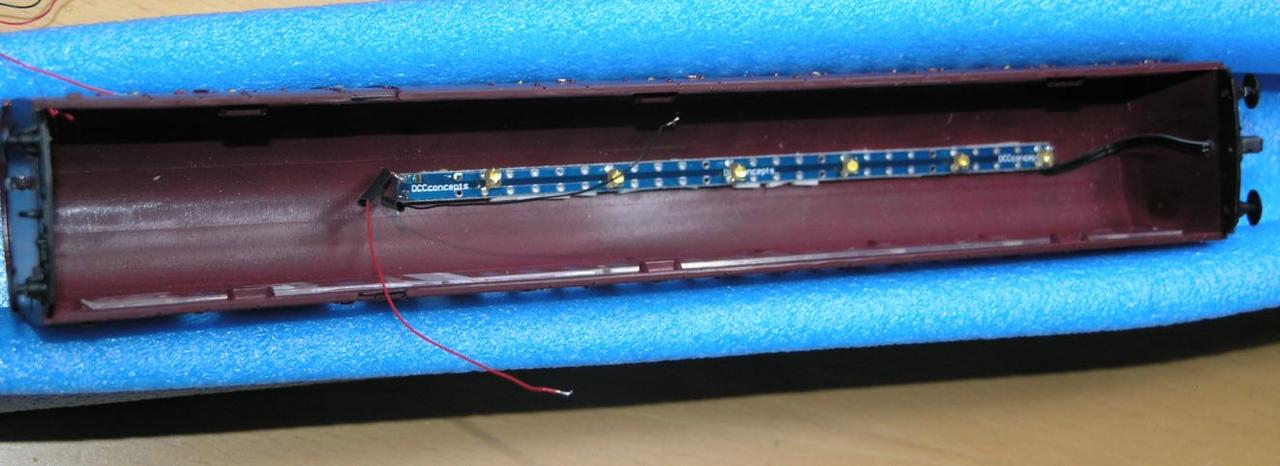
12V DC for DTM30 and SIGM20 boards as well as for Led building lighting circuits 15V DC for BDL168 and DAC20 boards 16V DC for Kadee electromagnetic uncouplers

Then I need the power supply for the DCC system.

As time goes by I will probably need at least one other supply - so a spare would be useful.

I decided to build a little control panel - inspired by the front panels used by "expat" aka Trevor of the MRF board.

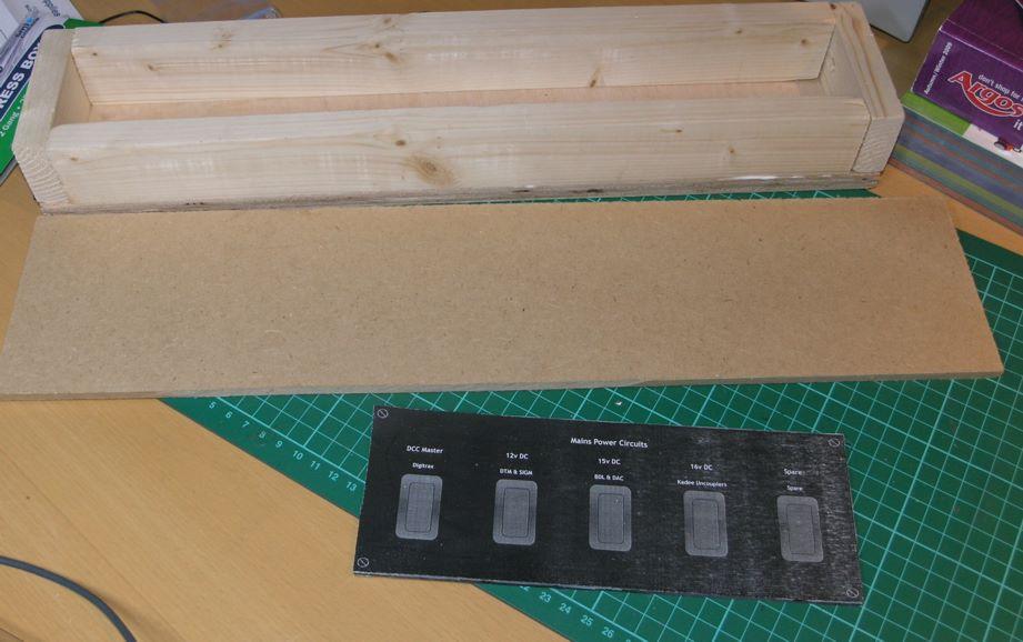
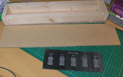
Here is the wooden box that I used to contain the wiring:-

/images1014/pwr_distrib_sml1.thumbnail.jpg

I mounted five mains sockets on the back:-

/images1014/pwr_distrib_sml2.thumbnail.jpg

The front panel is made of a 3mm acrylic sheet on which the switches are mounted and then this is screwed onto an MDF sheet which was painted black.

Here is the internal wiring:-

/images1014/pwr_distrib_sml3.thumbnail.jpg

I used a pile of heatshrink to cover up the terminals - what I had ignored was that when I got the wife's hairdryer to shrink the heat shrink - then it also bent the acrylic a bit - bother!

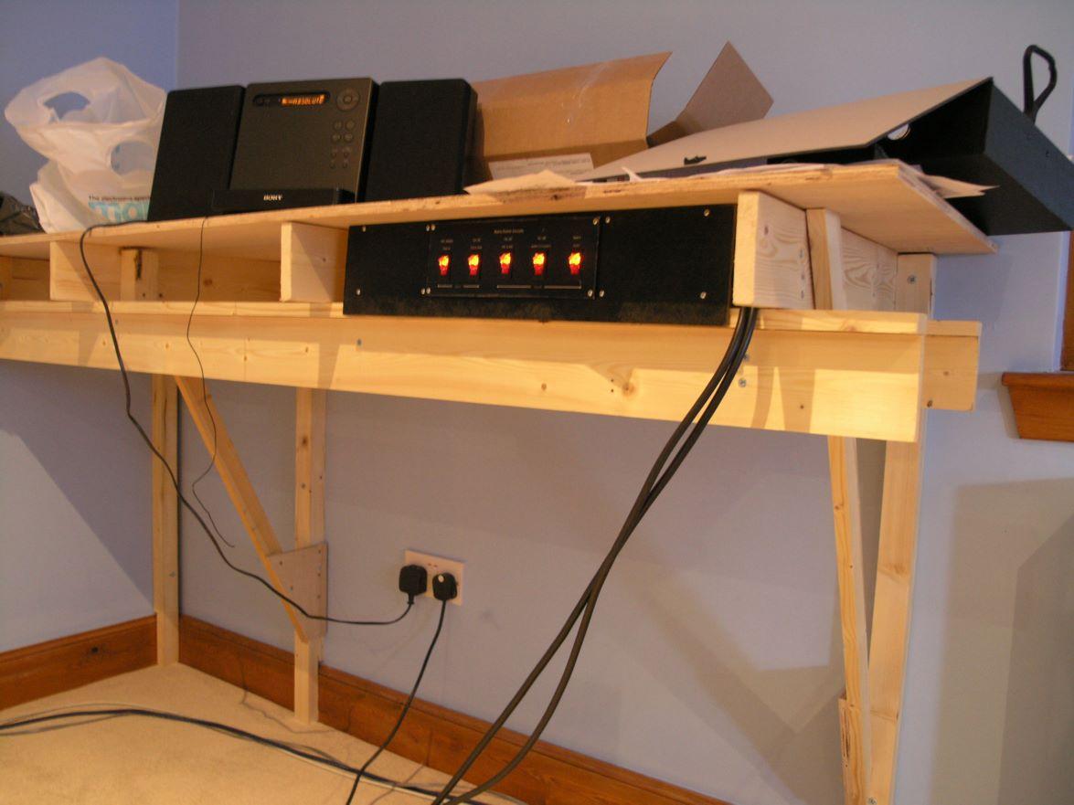
The whole unit is designed to slide into the front of the Lgirder benchwork I am using. so the width is largely dictated by the width of the studs in the wall! as these dictate the width of some of the cross pieces. Here is the rear view of the unit in situ:-

/images1014/pwr_distrib_sml4.thumbnail.jpg

I used illuminated rocker switches - as I am forgetful and it is a good way to see if I have left anything switched on.

The front labels are made by using heavy photo paper in the printer and then after it was printing giving it a coat of clear spray on varnish every day for five days. - it took several attempts and I am not completely happy with it even now.

Here is the front view - of the unit - but it is only resting in the bench as it is not in the final position - when it is finally positioned then the cables will be routed neatly out of the way.

/images1014/pwr_distrib_sml5.thumbnail.jpg

Latest Layout

Despite the fact that I have started to build the baseboards already I have not yet finished the track plan - I have just got bored with it.

The rear wall I am just going to have as a temporary simple shelf right now and will worry about a bigger better design later.

Here is where I currently am - I need to modify the station to add the curves that Banbury has - and I need to check a pile of dimensions.

/images1014/station_layout.thumbnail.jpg

Bachmann suburbans - part 8 Final Assembly

OK with all of the testing out of the way, now is the time for final assembly. Starting with securing the lamp strip PCB in the brake coach. As before I used the sticky pads supplied with the FF2 kit, and then cut a bit off the tops of the compartment partitions to allow it to fit. Careful positioning was necessary to allow the leds to fit 1 per compartment...

/images1014/fitted_strip.thumbnail.jpg

Then to provide a place to interconnect the pickup wires I superglued a small piece of tag strip on the floor of the interior moulding - immediately between the two access holes for the pickup wires.

/images1014/tag_strip.thumbnail.jpg

Finally I secured the two FF2 units and the FL2 decoder with some double sided auto foam tape. By this stage things are complicated as you have the pickup wires coming through the bogie through the chassis, through the interior moulding and secured onto the tag strip, and at the same time you have the wiring also connected to the rear lamp and the exterior moulding mounted pcb lamp strip - soo inevitably it ends up a bit of a birds nest.

/images1014/birds_nest.thumbnail.jpg

it is a bit of a fiddle to get all of the wires into the rear brake compartment as you reassmble all of the pieces and you may find the ready and frequent use of expletives helpful.

Once assembled - at least it worked - the lamps are perhaps a little too dim and subtle for my liking (or for good photography) but this is probably realisitic and certainly better than the ridiculously bright output you see on some models. I think if I do it again I will either choose some brighter LEDs or drive less off a single FF2.

Below are some pics of the finished job, the complete absence of flickering is excellent....

/images1014/tail_lamp3.thumbnail.jpg /images1014/tail_lamp1.thumbnail.jpg /images1014/tail_lamp2.thumbnail.jpg /images1014/interior_lights2.thumbnail.jpg /images1014/interior_lights.thumbnail.jpg

Bachmann suburbans - part 7: Programming the TCS FL2

This little project keeps throwing up problems that seem to cost a lot of time - firstly the locolamps not working, then the pull up circuitry to get the FL2 to work with the FF2 and now I hope a final problem - programming the FL2.

I don't want to do anything very sophisticated on the FL2 side but I did find that I couldn't use button 2 on the throttle to control the tail light (this is because on the digitrax throttle button 2 is not latching). Now there are various ways of programming DCC decoders - normally I only program on the programming track but on this occasion I used "ops mode programming" - in this the device does not need to be connected directly to the programming track instead the programming instructions are "sent" to its address and it can be on the main track.

Since my circuit was on my desk on the other side of the room from the programming track where i only had a connection to the main DCC rail supply I used ops mode programming. This worked fine to change the button for controlling the purple wire / locolamp - by loading CV 36 with value 16 I was able to change it to use button 3.

I was then stupid and went through the process of changing the FL2 to 4 digit DCC addressing, this is a multistage process and you first have to set CV 29 to 38 then load CVs 17 and 18 with some calculated values. The problem is that once you set CV 29 to 38 the "ops mode programming" ceases to work - as presumably the decoder is now at 4 digit address 0000 - only that isn't really a legal address and not one that you can use the digitrax to send stuff to. The decoder is now lost in (address) space. So now the only way of controlling the decoder until you have sorted this out is to put it on the programming track.

The problem I then found (and reading various internet boards I am not alone) is that I was unable to get the FL2 to respond on the programming track - argh!

I contacted TCS support who suggest a few things - but eventually I found the following - programming on the programming track only works if I disconnect the FL2 from the FF2s - The circuit I used was maybe over the top - but I put a resistor and LED on one funciont wire - the LED will then flash when programming happens giving you some visual feedback - I also connected a 47ohm resistor across one of the function wires and the blue return wire on the FL2. There was conflicting info from TCS if this was necessary or not - the instructions said yes but the support people said no.

Because the FL2 comes with a separate harness at least you can make up a harness for programming on the programming track to set four digit addresses and then do all other programming in "ops mode" on the main.

Circuit I used for programming the FL2 on the programming track using a digitrax DCC system...

/images1014/Programming_Harness_FL2.thumbnail.jpg

Bachmann suburbans - part 6: Circuit Diagram

So I have ended up using two FlickerFree units to control the two sets of lights - one FF2 to control the carriage light and one to control the rear light. The rear light you could just control from the FL2 and live with the flickering but I have decided not to.

Here is the circuit that I ended up with after much messing about...note that there are actually twelve tiny leds for the carriage lights - only four are shown..also note that the two resistor values are not to be confused 47Kohm is required for the locolamp -less than 10K would probably damage it- wheras 47ohm is required to get the 12 carriage lights to have the sort of brightness one might want (less than you initially think).

/images1014/SubCircuitCropped.thumbnail.jpg