
Bachmann suburbans - part 5: Bogie conversion

The first job to do on the bogie was to change it to a Kadee coupling

I am using the technique I found by a contributor to Model Rail Forum LINK}:-http://www.modelrailforum.com/forums/index.php?showtopic=11303;here; Which involves unscrewing the coupling bracket and then cut off the vertical section that holds the old tension lock then drill a hole as far forward as you dare in the now forward most horizontal section of what remains. Use that hole to bolt on a Kadee 46 and then remount the whole unit upside down - voila its magically at the correct height.

PIC}:-kadee46suburban.jpg;

After fitting the kadee then on the rearmost bogie of the brake van (i.e. the one underneath the guards/parcel area where we are going to locate the electronics) then I fitted the brelec pickups - these are expensive and fiddly - especially getting the little 'rivet' to go through the hole you have to drill without dropping everything and having to crawl around on the floor to find all the pieces (repeat until you get fed up). I will reserve judgement on whether cost/effort was worth it until i see how they work.

/images1014/Kadee46suburban.thumbnail.JPG /images1014/P9173084a.thumbnail.jpg

Bachmann suburbans - part 4 Fixing Leds

Looking back on some earlier advice from Richard of DCC concepts on use of Flicker Free with FL2 I realised that what was missing (though you won't find instructions to tell you this anywhere).

You need to connect the blue 'return' wire on the FL2 to the green wire of the FF2 via a pull up resistor (10K seems to be fine).

Doing this and voila I now have DCC control over the lights via the TCS FL2 decoder and the FlickerFree unit.

[I will put up a circuit diagram when I have finished tweaking later on].

So I went ahead and fitted the strips of LEDs into the open carriage.

PIC}:-LEDstrips.jpg;

My next job is to fit the DCC concepts LocoLamp onto the back of the brake coach. It is amazingly small - it is marked here with a red arrow.

/images1014/locolampOnSuburban.thumbnail.jpg

It isn't brilliantly positioned and I have just used regular plastic kit glue to fix it.

Getting to the point where I was confident enough to fix the locolamp was a long story - I had a whole pack of them (thirty quids worth) that just didn't seem to want to work for me - they are easy to blow up but even so! That pack has been sitting in my cupboard for several years so in frustration I purahcsed a new pack and these seem to work fine.

One trick to learn is how to remove the enamel insulation of the tiny leads that supply the locolamp. There are several techniques - you can burn it off - but this is a bit uncontrolled, or you can gently wipe with an emery cloth being careful to put no strain on the connection - neither are great. and stripping the insulation remains a bit of an art form.

/images1014/ledstrips.thumbnail.jpg

Bachmann suburbans - part 3: Microconnectors

I have lashed up a simple set of connections between the FL2 decoder and the DCC concepts FlickerFree2 device and the lighting strip - initially this does not seem to work.

Pressing button 1 on the controller should toggle the lights on and off - but it doesn't.

So while I scratch my head about that I have drilled some holes in the ends of the carriages for the Miniatronics microconnectors.

They are only an interference / friction fit at the moment - and O am hoping they can stay that way.

/images1014/P9063073.thumbnail.jpg /images1014/P9063075.thumbnail.jpg

Upgrading the Bachmann Suburbans - Part 2: Bill of Material

By connecting the carriages I can control their lighting as a single unit which is nice and also I lower the cost of the fit out by using only one decoder and one FlickerFree unit.

The Flicker free units were devised by Richard of DCC concepts for DC originally - and they contain a large capacitor to drive the leds even when pickups aren't working - e.g. when train is stationary. Of course on DCC when the train is stationary the rails are still live - but the FF2 still has a purpose - firstly it allows more LEDs to be driven than a typical lighting decoder - and in the packs you also get the really hand lighting strip PCBs and some nice microdot LEDS that are ideal. The FlickerFree2 pack come slike this...

/images1014/flickerfree2pack.thumbnail.jpg

and once opened you can see lighting strips FF2 units leds and a handy pack of 1K resistors.

/images1014/ffreepackcontents.thumbnail.jpg

So now I have my complete bill of material - and it looks something like this -

Seated passengers - From ebay seller everest model on ebay £8.99 for 60pcs Kadee couplings - in stock but probably around £5 for a pack Pickups - Brelec - bought from DCC Supplies - £4.50 FlickerFree2 from DCC concepts bought from Digitrains - £58.32 for pack of 6 Microconnectors - Miniatronics bought from Digitrains - £8.32 for pack of 2 pairs DCC Decoder - TCS FL2 lighting only decoder bought from Digitrains - £14.82

PIC}:-Wholekit.jpg;

I did consider using electrical connector couplings but as their are no NEM coupling sockets this would have been hard. I am also trying the brelec pickups to see if they are easier than just a bit of bent pickup wire. The axles on the suburbans are not conductive at all and so

So overall if you take one sixth of the FF2 pack and passengers set and a half of the connector pack then you get a total cost for the pair of carriages of around ( (8.99 + 58.32) / 6 ) + ( 8.32 / 2) + 14.82 + 5 + 4.50 = £39.70

Which will almost double the cost of the two carriages which are currently retailing for around £19 each online.

/images1014/WholeKit.thumbnail.jpg

Upgrading the Bachmann Suburbans

I like the Bachmann suburban coaches they fit in well with the time and place of where I am proposing to model (Banbury 1962) but as models they are rather dated in a number of areas. For example they do not have NEM couplings.

Here is a slightly out of focus picture of one -

/images1014/bachy_sub_poorfocus.thumbnail.jpg

I have one pair of these coaches and they will always run together. So I would like to do the following -

Add some passengers Add lighting (both interior and rear oil lamp) Change the couplings to Kadee

To add the lighting then there are choices to be made - do I want to have DCC control of the lights?, how am I going to make the pickups work? do I want each coach to be independently controlled and fed with power or shall I have them as a pair?

In fact in this case it is an easy decision - as these coaches will always run as a pair - I think the thing to do is put a single DCC decoder in the brake compartment and then join the coaches electrically by some means - this means putting the pickups on the same coach as the decoder only.

I will cover the choices of components in more detail in the next post - in the meantime here is how to take the coaches apart...

The first task is to remove the bogies - simples - undo the obvious centre screw in each. Removing the body is a little harder - it is held by six clips on the body that need to be prised away from the cut outs in the side of the base plastic.

/images1014/removingthebase.thumbnail.jpg

Once the body is off then you find that the same six clips that held the body to the base also hold the interior mouding in place - the interior moulding needs to be prised over the clips

/images1014/gettinginside.thumbnail.jpg

Once inside my first job was to glue in some lucky passengers using regular airfix type glue - in this case Revell Contacta.

/images1014/passengers.thumbnail.jpg

OK those are the easy bits done, next I have to work on the harder stuff of electronics and connections before doing the very tricky looking hack to get Kadee couplers to work with the stock.

DCC conversion on a Bachmann 4MT 4-6-0

I don't write up most of the DCC conversions - only those ones are slightly tricky - as much for my own aide meoir as anything else.

I have recently added a decoder to a Bachmann 4MT 4-6-0 - getting the body off is not too bad - as long as you identify the right screws - to get to the front one you have to look under the front bogie - an access hole is provided in the bogie to get at it. The rear one requires the brake work plastic to be moved to one side - as shown below.

PIC}:-rear4MT.jpg;

Once the body is off then I found my favourite TCS DP2X-UK wouldn't fit in the space and went for a decoder with a harness - shown here is the Bachmann three function decoder. I have had problems with these before and the only reason I used it here was that it was the best fit into the space in the boiler...

PIC}:-inside4MT.jpg;

In fact I got very erratic running (loco suddenly bolting and suddenly locking still) so I gave that up as a bad job and went for a LENZ silver instead which was harder to fit in the boiler space but works perfectly.

/images1014/rear4mt.thumbnail.jpg /images1014/inside4mt.thumbnail.jpg

I am not dead!

Several things have prevented me from updating this blog.

Firstly - and slightly curiously was the removal of applescript support from CyberDuck. Cyberduck is the FTP software that I use and it used to support scripting, this allowed me to upload only changed files over my incredibly slow internet connection to the hosting server.

This blog is produced using a homebrew software suite written in Objective-C (as a learning exercise for me) to make the system work sensibly I have had to hack the system so it only updates changed files (it used to rewrite all files in the blog from a clean slate on each change) in this way I can now only upload files that are changed using Cyberduck inbuilt sync - and that will in turn mean it is actually practical for me to update the blog.

Anyway - now back to the modelling and next item will be a catch up with where I am.

Electrical Pick-Ups, Occupancy Detection and LEDs

As part of my grand plan, I need to get good occupancy detection of trains on the layout. Achieving this is easy for locos - the Digitrax BDL168s referred to in earlier posts see the loco current draw and know it is in the relevant section - however the occupancy detection really needs to see the rear of the train as well as the loco at the front. Therefore I decided as a test to try and convert a brake van to trigger the occupancy detection.

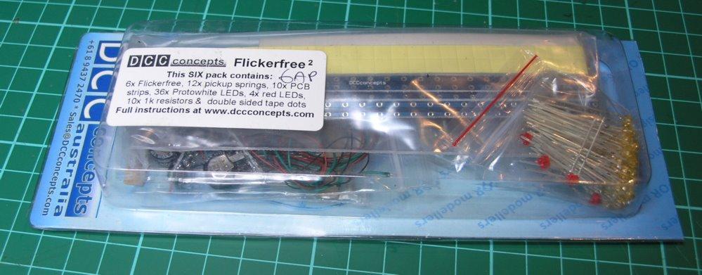
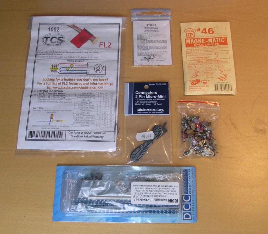
While I am at it, I will also try and add some LEDs to the brake van to provide some lighting effects, in particular I want to try some of these fantastic looking LINK}:-http://www.dccconcepts.com/index_files/DCC_loco_lamps.htm;oil lamps; from DCCConcepts.

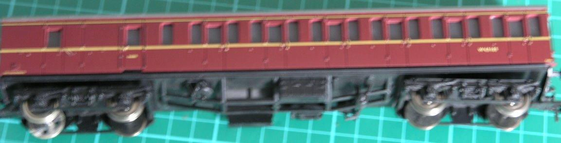
I started with a LINK}:-http://www.ehattons.com/StockDetail.aspx?SID=23584;Bachmann 33-306A; toad brake van.

Now the two aims - lighting and occupancy detection - both require electrical pick up from the track - this is not that easy at least for me it isn't. By default Bachmann insulate both wheels where they join with the axles - obviously if there was no insulation then the wheel / axle combinations would short the two rails out.

I intended to use the LINK}:-http://www.dccconcepts.com/index_files/DCCflickerfree.htm#Pickup%20Spring;DCCConcepts pickup srings; which fit over the axles but these need one of the wheels to be electrically connected to the axle. My initial attempt was using silver paint

/images0509/silverpaint.thumbnail.jpg

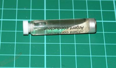
but i just couldn't make this work - the paint is a suspension of silver and even after repeated attempts i couldn't get any electrical connection from the wheel to the axle. So on to plan b - more expensive - but more reliable perhaps. Replace the wheel sets for ones that have an metal bush on one wheel thereby making the axle 'live'.

One company that advertise live axles are LINK}:-http://www.btinternet.com/~markits/;Markits;

I ordered two Markits wheel sets the 12mm for the brake van, and the 14 for a Bachmann Mark 1 coach - that I wanted the same treatment for.

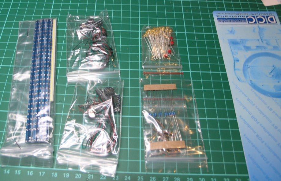
2 X MRJ12TSNSL1 (12mm 10 spoke n/s live 26mm Axle) 2 X MRJ14BR1-1L (14mm 3' 7" contoured n/s coach disc live 26mm Axle)

These were not cheap, by the time postage was included these four axles cost 15 pounds. Worse the van really needed 13mm wheels and putting the smaller ones on it, meant that now the van was too low for the kadee height test...

/images0509/toolow.thumbnail.jpg

Still I carried on anyway, thinking that if the project worked I could always go for some larger wheels later - the model came with 13mm wheels but Markits only do 12 or 14mm - and fitted the spring takeoffs to the axles ... you need some calipers to reset the wheel axle widths after you have done this.

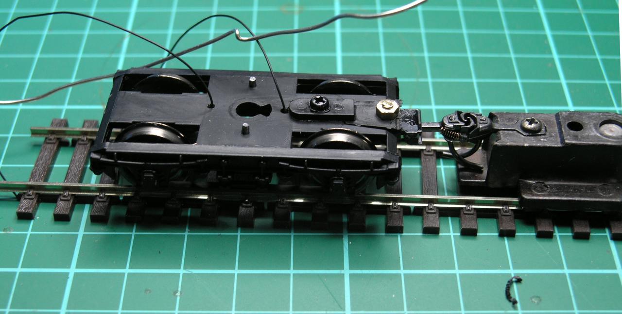
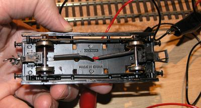
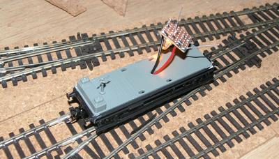
The I soldered some insulated wire to the springs and covered the join with some heatshrink. So the underside looked like this -

/images0509/pickuparrangement.thumbnail.jpg

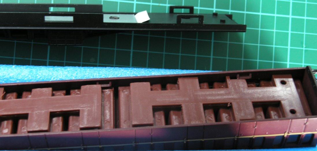
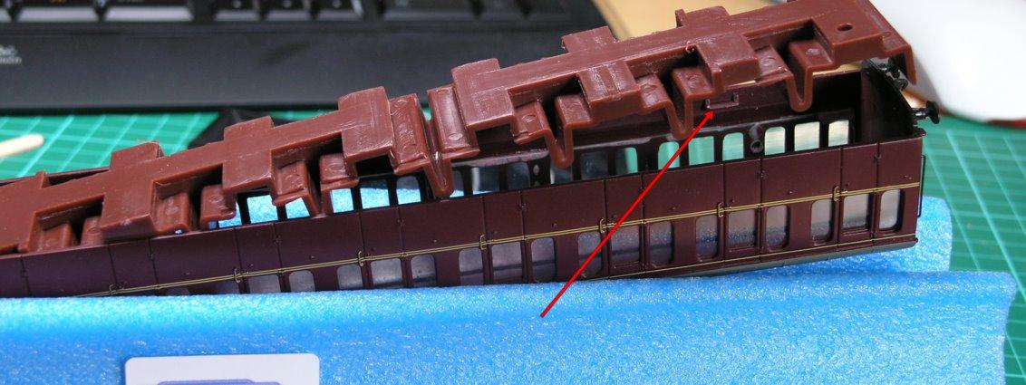
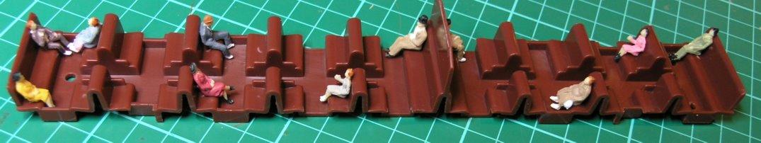
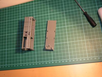
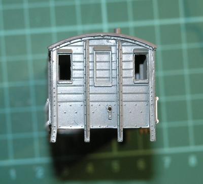
To get the wires through the chassis I needed to drill a hole in the floor of the brake van, and to do this I had to prise the body off - the body is glued to the (black) chassis, and the body has a (grey) floor that is also glued in place and can also be (carefully) prised out. We also need to get into the body later to place various bits of circuitry and the interior LED. Here is the body separated from the floor prior to drilling...

/images0509/bvbody.thumbnail.jpg

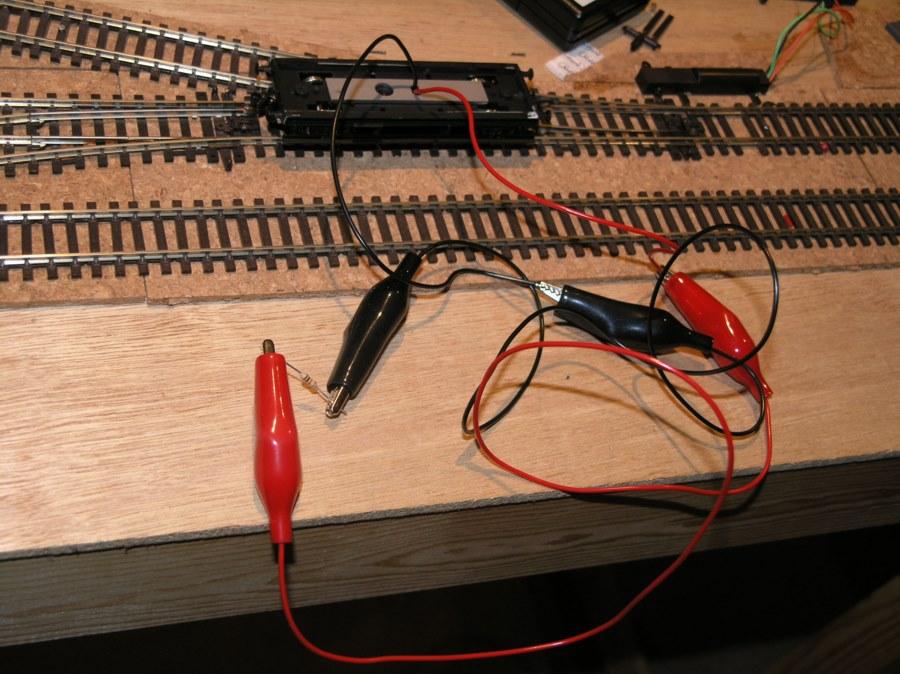
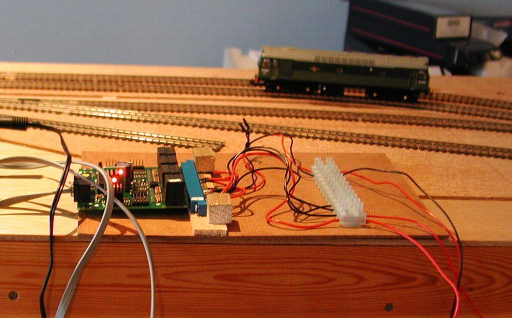
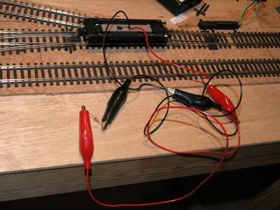
Next came a very simple occupancy test - if you place a 10K resistor across two rails then that is sufficient to fire the BDL168 to show occupancy, but far too small to short the track or cause any significant current to flow. So next I tookthe two wires exiting from the top of the chassis and connect to a 10K resistor with some croc clips and voila my Heath-Robinson looking device is detected by the BDL168s.

/images0509/occupancytest.thumbnail.jpg

Now having got power to above the chassis in the brake van - i need to work out what circuitry i need to both power the two very different LEDs and to make the occupancy work.

Now DCC is an odd sort of supply as it is squarewave AC - and so i asked Pearson(elder) for advice - you can see his response here (broken link).

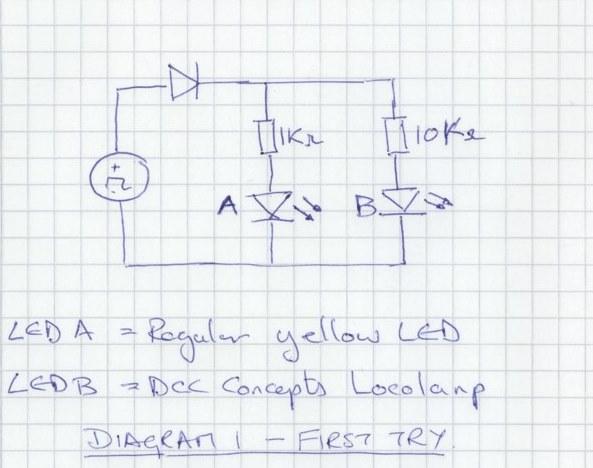
So from that I believe that I need to adopt the following circuit. The choice of 10K for the locolamp is not from any theory but because the resistors supplied in the pack from DCC concepts seemed to range from 5kohm to 20kohm - so obviously they expect a very low forward voltage.

/images0509/circuitdiagram1.thumbnail.jpg

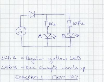
I lashed up a crude test of this with some components and sure enough it triggered the occupancy detector and lit LED 1 but not LED 2 ( the locolamp).

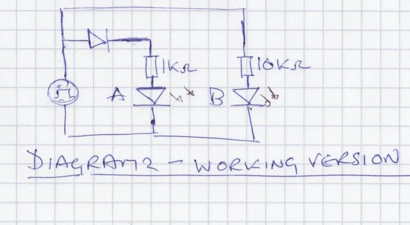
A bit more messing around led me to the following answer...

/images0509/circuitdiagram2.thumbnail.jpg

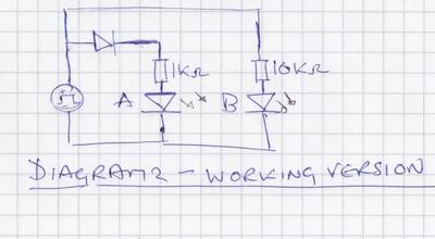
If like me you are a bit unused to identifying diodes then really anything that isn't a zener is likely to work - ideally look for a minimum breakdown voltage of > 50V other than that go for a nice small size that will fit in your model!

I built this circuit on a little bit of veroboard cut from a larger piece bought at maplin and using a yellow LED from Rapid that I had in stock - yellow to simulate an oil lamp lighting the inside of the vehicle.

/images0509/cboard.thumbnail.jpg

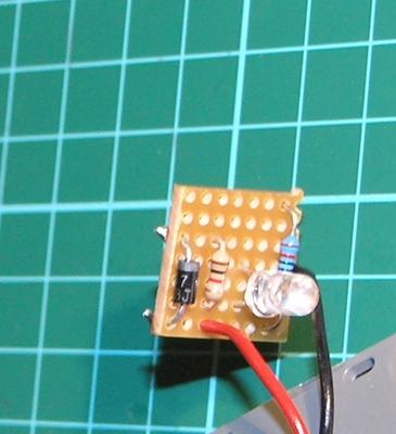
Here is the circuitboard mounted on the van base - with the led being lit...

/images0509/ledworking.thumbnail.jpg

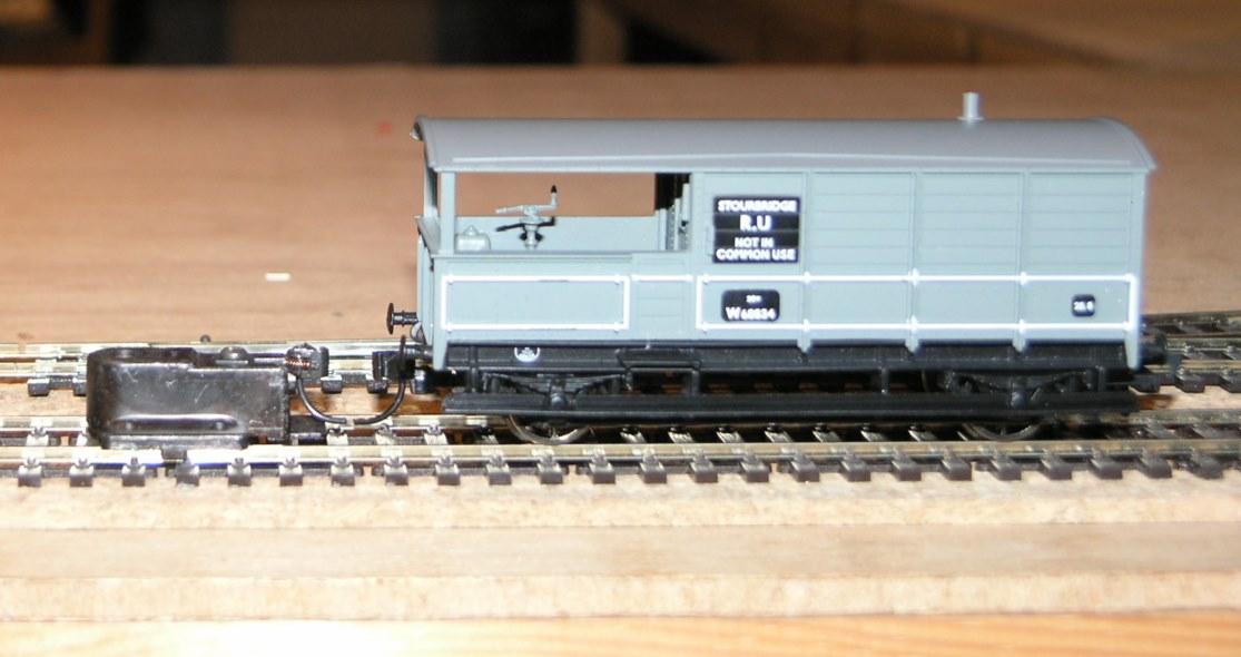
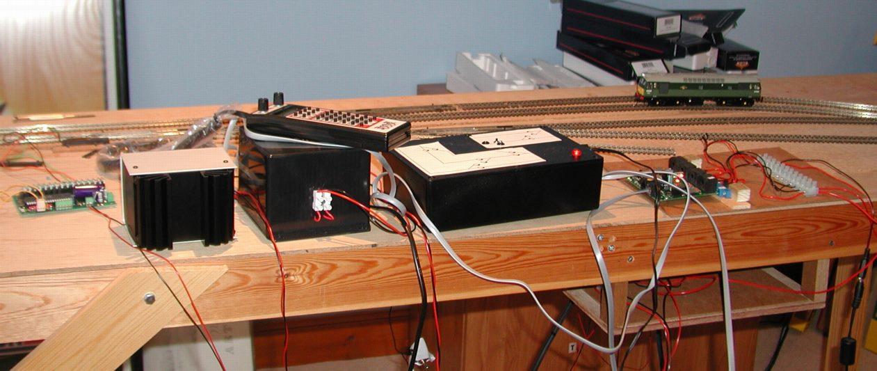
And even more satisfying here it is both stopping an oncoming loco and turning the associated signal to red - via the CML SIGM20 I mentioned earlier in the blog.

/images0509/stoppeak.thumbnail.jpg

Disappointingly though the connection via the rails up to the circuit board is too poor to work well for occupancy detection. The led flickers all of the time as the van circulates on the track - i could fix this using a capacitor circuit like flickerfree (also from DCCConcepts) but this won't help with the occupancy issues. If the computer and/or signals see the occupancy going on and off they will get confused. A bit of messing about shows the problem is not the spring pickups on the axles but the fact that the two live wheels aren't always in contact with the rail.

Accordingly I am going to have to try and get eletrical pick up from the other two wheels on the van and probably also weight the van down more. This will mean fiddling about with nickel silver springy wire - not something i am looking forward to.

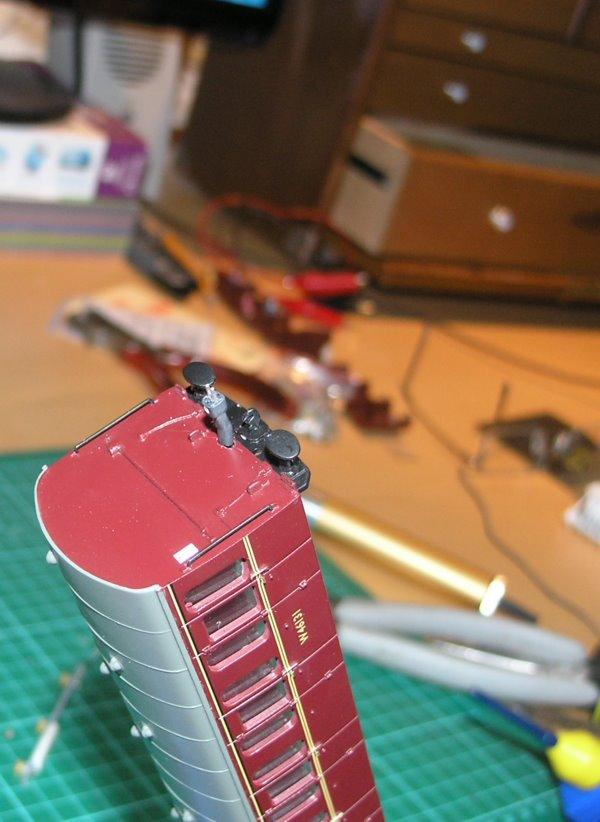
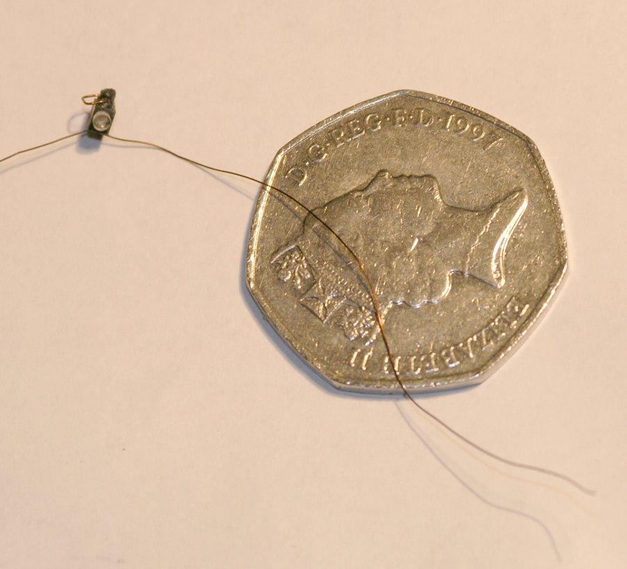
So in the meantime I have been messing with the locolamp. These are really incredibly small.

/images0509/locolamp.thumbnail.jpg

They come with enamel coating over the wires for insulation. This is not easy to remove - I finally did it with a combination of a match to burn the enamel off and a piece of emery cloth.

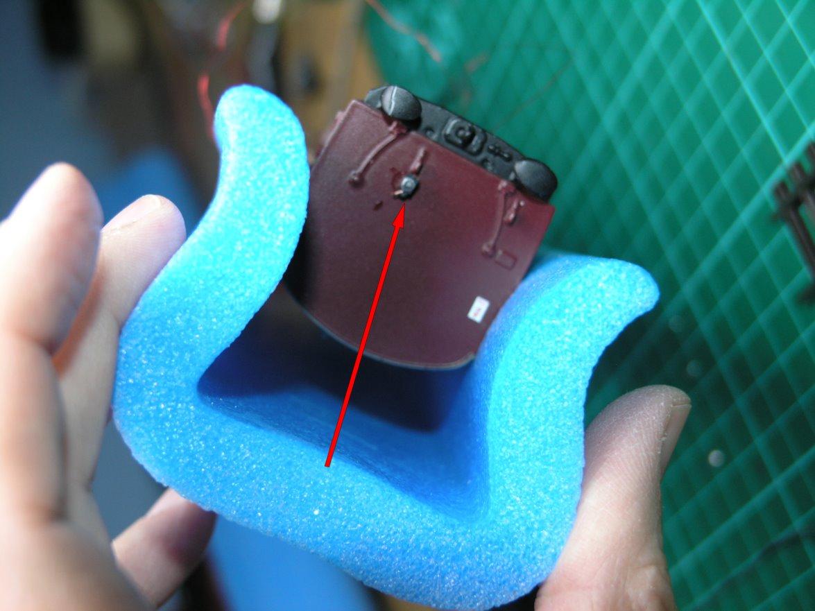
Here is the hole drilled on the van for the red oil liamp light...

/images0509/lampirondrill.thumbnail.jpg

More when I try and connect a pickup to the other two wheels.

Block Detection Visible on Computer

Here is the first screen showing a live block occupancy detection on demo version of RR&Co software.

As the loco enters the section the block turns from yellow to red and as it leaves it turns back to yellow again.

Now I just need to try putting three separate detection sections into a single logical block.

/images0509/first_block_detection_screen.thumbnail.JPG

Block Occupancy Detection

A key part of the infrastructure on the planned railway is 'block occupancy detection' - a set of circuitry that allows you to know if part of the track is occupied.

For this I am using the BDL 168 from Digitrax. It is suitable for the other loconet devices that I am running For example it tells the DTM30 that a section of track is occupied via loconet avoiding lots of long wires for LED displays, it also interacts with SIGM20 signal controller to automatically control signals, and finally it provides vital information to the computer to allow it to automagically run trains, and hopefully avoid crashes.

It took me sometime to understand the wiring diagrams, they are highly ambiguous - but for my simple test setup you just connect Zone Common wire to the main Rail A feed. then for the section to be detected remove the Rail A wire from wherever it was previously connected and join to any of the 16 detection section pins on the DBL connector. And that is it.

Learning points - I will need to plan lots of rail gaps and feeds into the layout before construction to allow sectioning.

Here is the board and connector mounted on a scrap piece of hardboard :-

/images0509/bdl168mounted.thumbnail.jpg

And here is it working for the first time, the top LED indicates that the class 25 at the back of the shot is 'in section'.

/images0509/in_operation.thumbnail.jpg

And finally here is the full array of electronics I am currently using -

/images0509/wires_everywhere.thumbnail.jpg

From the left we have a Team Digital SMD 82 static controller that is operating the one point motor, then the Digitrax controller and PSU and then comes the box containing the CML DTM 30 and finally the DBDL168. I still have to add a SIGM20 and replace the SMD82 with a CML DAC 10.