
North End Of Fiddle Yard Electrics

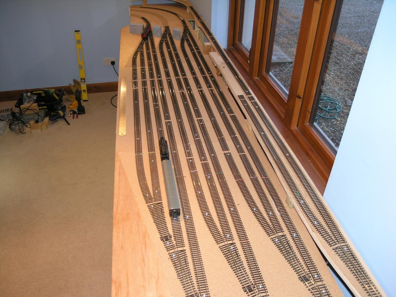
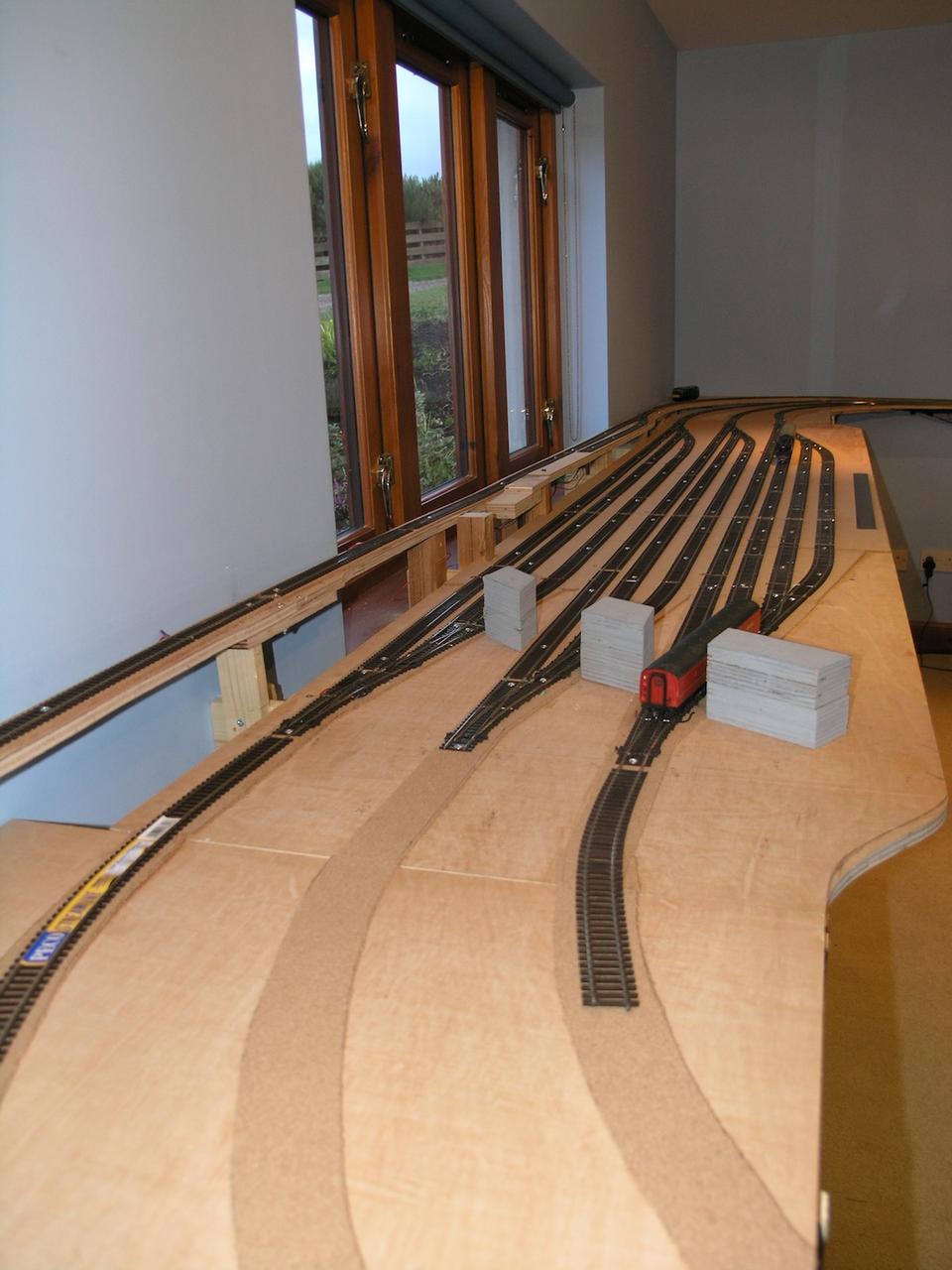
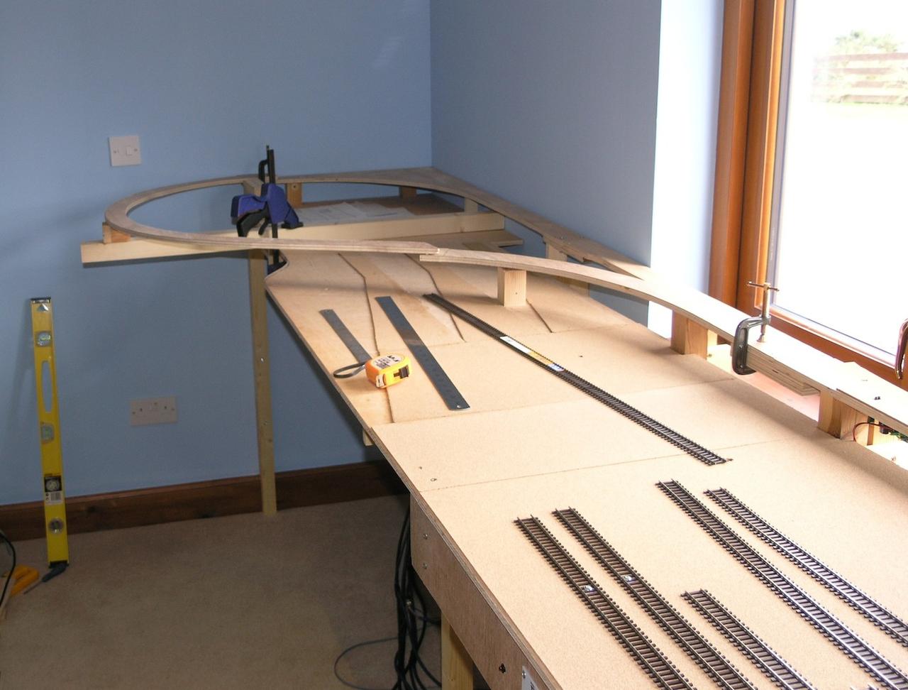
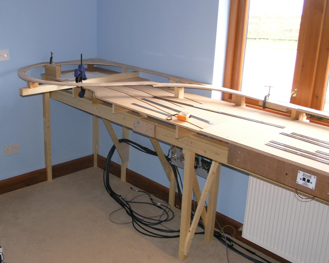
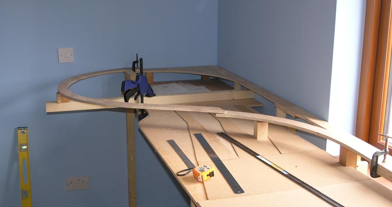
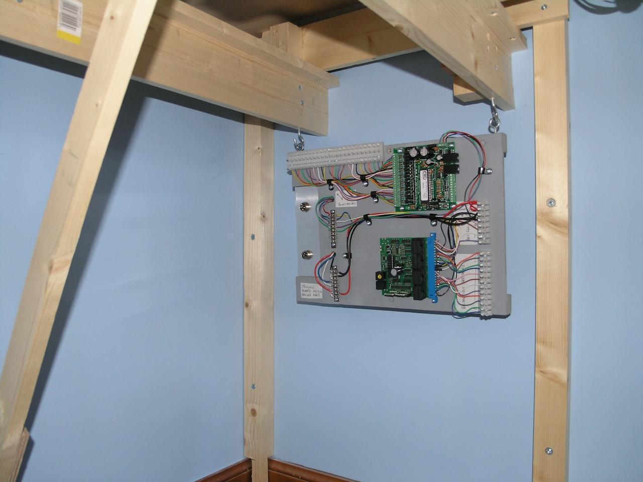
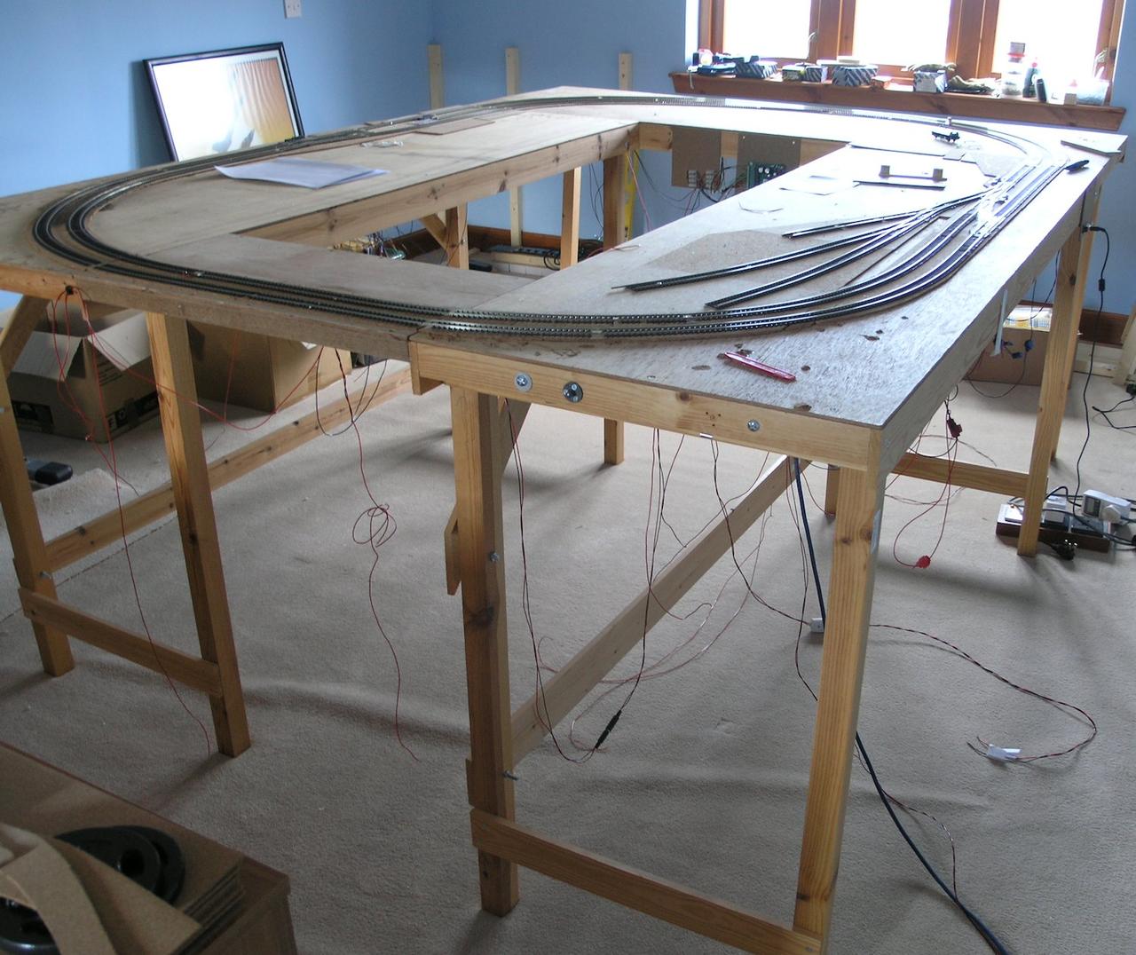
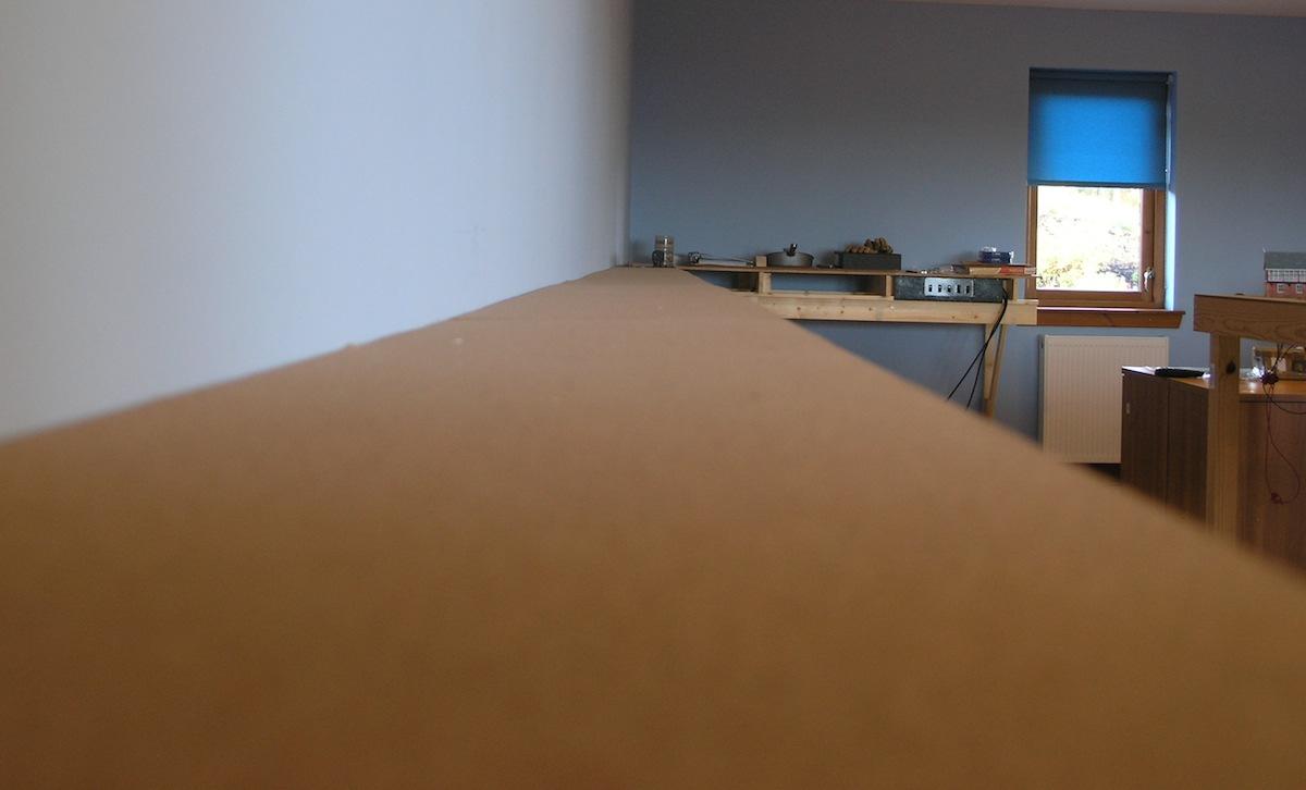
I have now just about completed the under circuit wiring for the North End of the Fiddle Yard (actually it is only North by orientation of the room - on the modelled location it would be the South end) - Becuase I am so incapable of working upside down these days I made the board with track breaks at both ends so that it could be lifted up later - although the overpass track will need to be removed.

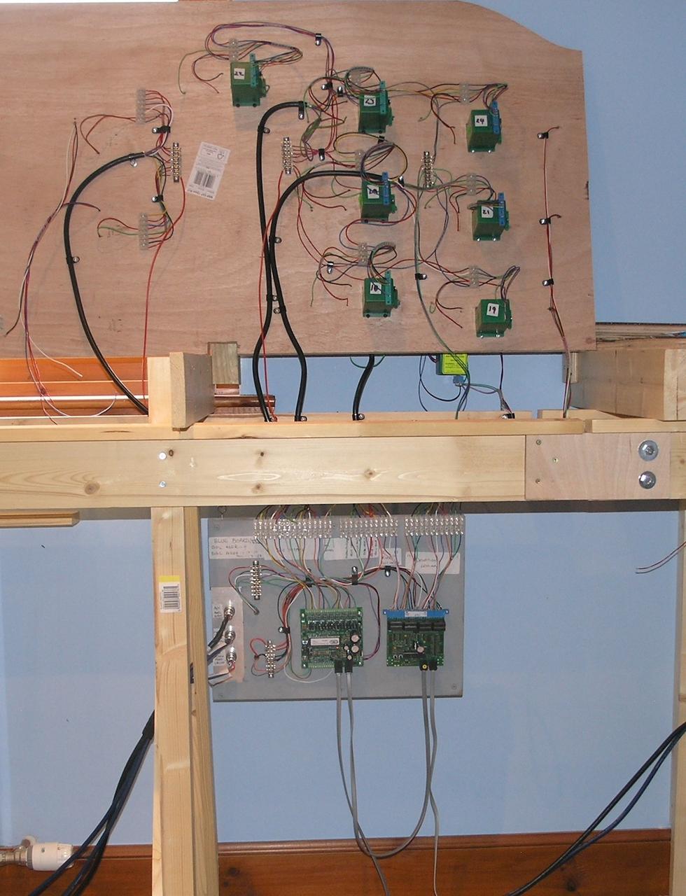
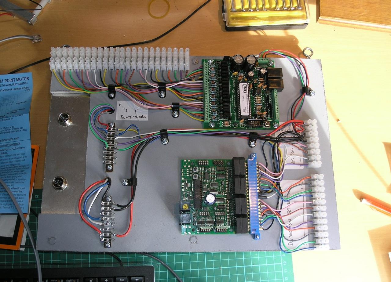
The electrics have taken a long time, as there are something like 35 different track feeds to the yard (in order to get occupancy information) as well as 14 points that each need polarity switching for electrofrog and point motors connecting up.

You don't actually have to do polarity switching as the points do it internally these days but the mechanism is not the most robust so I use prefer to do motor contolled polarity switching.

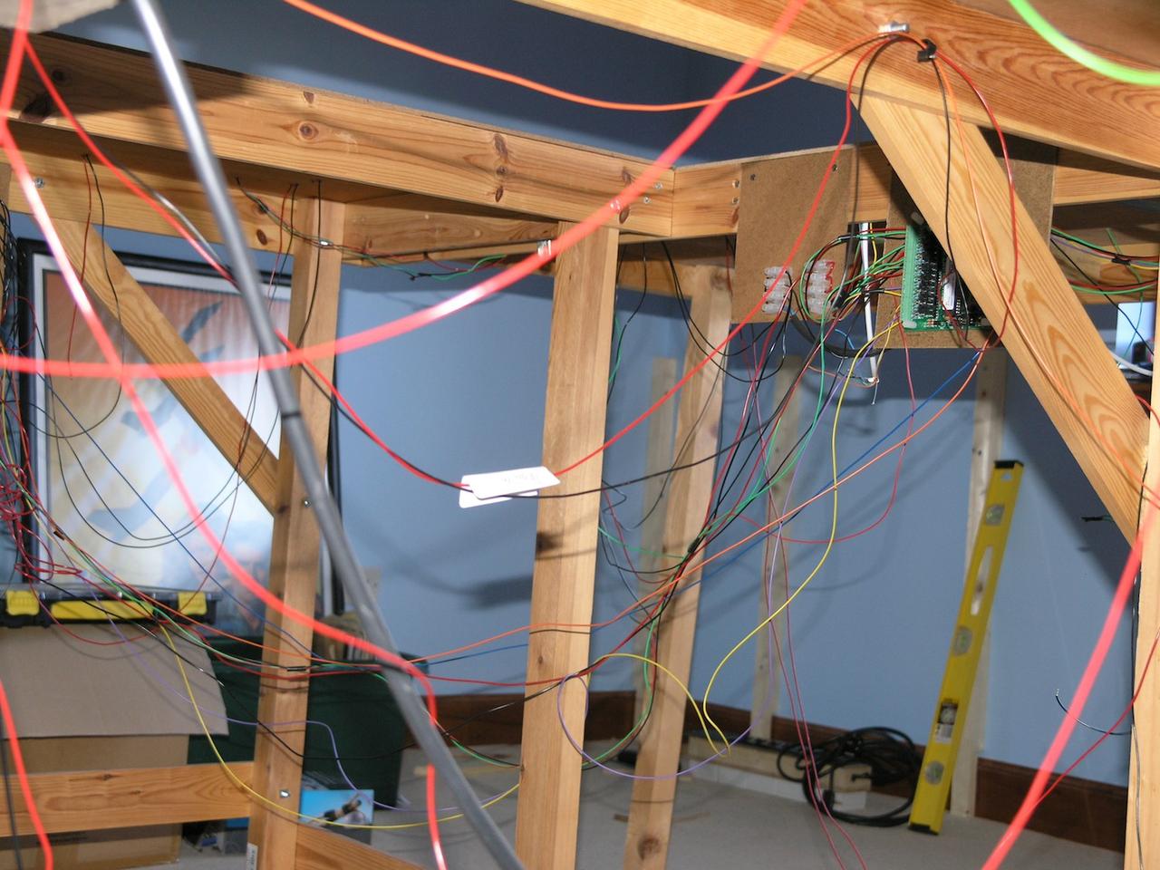
Because some occupancy sections cross the board break I have to do some cross wiring to the South side and vice versa which adds some complexity. As ever I am fighting to keep it neat.

Still at least it all seems to work.

/images1014/Model_Railway_North_Fiddle_Yard_Wiring_Reference_Picture.thumbnail.jpg

Fiddle Yard fairly Complete

I am just about done with it now - here are some pictures. The grey blocks are the supports for the reversing loop overpass that I can't complete until I have built the baseboards along the adjacent wall - as they contain some supports for it.

Making the supports exactly the right height and to a very odd cross section has been hard - eventually I glued three pieces of 24mm ply toegther and that is about right.

/images1014/FYfromabove.thumbnail.jpg /images1014/FYnearlydone1.thumbnail.jpg /images1014/FYLookingalong.thumbnail.jpg

Overpass

I have been working on the woodwork for the North end of the fiddle yard and the overpass for the reversing loop.

The reversing loop itself has two different gradients - shallower on the way up - and steeper on the way down - necessary to give good clearance across the tracks but also not kill the locos when pulling long trains.

The up gradient is about 1 in 60 with approx no gradient at all around the curve of the overpass.

Curves and gradients are really hard for the rolling stock to cope with.

The overpass sections have been cut out of 12mm ply with a jig saw after printing out the template from xtrackcad.

/images1014/overpassclamp3.thumbnail.jpg /images1014/overpassclamp2.thumbnail.jpg /images1014/overpassclamp1.thumbnail.jpg

Two Wire DCC HaHa

For the last three weeks I have been fitting the point motors and wiring up the South end of the fiddle yard - even after taking great care to try and keep the wiring neat it still looks a bit of a birds nest.....

/images1014/P8223356.thumbnail.JPG

Fiddle Yard Construction

I have spent much of the last few months making slow but steady progress - I have built four of the control boards I need - including the power distribution board which contains 2 x PM42 power distribution thingys from Digitrax. This allows the network to be separated into a number of separate power feeds - on a large layout like this it also helps short circuit detection in that you can immediately see which area of the network you have a short on. Finally it does the job of inverting the polarity for the reversing loop. The power distribution board also distributes three other AC and DC supplies for powering various things - You can see it propped up on top of the basebaord on the left of this picture...

/images1014/FiddleYard_in_Progress.thumbnail.jpg

It does seem though that I have enough power feeds to supply a good section of the london underground!

I have also installed under the reversing loop slope section an infra-red detector to automatically change the reversing loop point whenever a train is approaching it. This works well apart from the fact that it doesn't always initialise to the correct orientation - I have not investigated cause or solutions to that yet.

Hopefully I can now lay the track for the fiddle yard quickly as I have built the control boards to supply all of the points - 14 or so and all of the detection sections 28 or so.

One of the reasons for my lack of updates on this blog is the update to Mac OS X 7 - my own blog writing software (written in objective-c) used older Operating Sytem calls no longer supported in OSX 7.x so I had to open up the software and fix it - a trivial job in itself but downloading the latest development environment on my slow link and educating my slow brain in the changes to the OS API was a big obstacle! .. thumbnail:: /images1014/FiddleYardBaseboards.jpg

Hello to clean room

Now that the test layout has gone the room has been cleaned ready for the new track to be built. So far only the back wall shelf and two 2 metre wallmounted benches have been assembled.

/images1014/relayed_carpet.thumbnail.jpg

Goodbye to the old test track

Back in December 2006 I decided to build a model railway. I decided as things had moved on som much since I last did model railways I would build a test track. A single bench about a meter high was built to test out DCC and the like. Subsequently in March 2009 I expanded that to a circuit on three benches and integrated that over the following year with block detection, computer control, automatic signalling etc. etc.

But it has outlived its usefulness and this photo was taken at the start of the week before I salvaged what I could from it in components and wood. It has now gone completely.

PIC}:-test layout;

One of the main things I (re)learnt was that if you want to do occupancy detection and so on the wiring becomes and absolute mess unless you work really really hard to get control of it. As I knew the test layout was never long term I made no real effort to control it and as a result it became quite a shameful pickle.

/images1014/shameful_wiring.thumbnail.jpg

The new layout is much bigger - consuming a room of 7.5m by 4.5m and has over 40 points - a number of which are slips requiring two point motors. Accordingly the wiring needs much more thought.

I have decided that each of the major areas will have one or two control boards on which PCBs etc. are mounted. With connectors back to a main power distribution board which distributes DCC track power (via a Digitrax PM42) and also other power supplies required for running the various circuit boards.

My first control board is now finished, it has no signalling element on it as it is for a non-scenic part of the layout. It has been tested and operates correctly showing track occupancy and operating point motors. I wanted to get this working before I tore up the test layout in case that contained any lessons on how to wire the various devices.

/images1014/control_board_on_bench2.thumbnail.jpg

The control boards (I think there will be 6 or so) are designed to hang underneath the layout, on two simple hooks.

/images1014/control_board_in_situ.thumbnail.jpg

Part of the plan is never to have to do the dangerous sport of upside down soldering!!

/images1014/test_layout.thumbnail.jpg

A diversion into Railbus DCC fitting

As proof that I don't learn from my mistakes - I am an absolute sucker for new models. The rational part of my brain tells me it will mean frustration and expense but that never seems to get control when something nice appears on the website of my favourite Internet retailer.

The latest example of this is the lovely looking Heljan railbus in dark green with speed whiskers. Ordered it on a whim earlier this week and as soon as it arrived I attempted to convert it to DCC.

It is nicely packed in the standard Heljan box, it is also a wonderfully heavy model - there is a real heft to it.

/images1014/railbuspackaging.thumbnail.jpg

To fit the DCC decoder, the first job is to prise off the two airhorns - to reveal two fixing screws - it is quite hard to do this without damage - I found a scriber was the best tool.

/images1014/airhornremoval.thumbnail.jpg

The hardest job then is to remove the top half of the body - note the instructions in the box do not mention that you MUST carefully remove one end of the two metal hand rails or when you split the body they will fly across the room.

You have to prise the bottom of the doors away from their seating and slightly outwards to allow the top to come off - this is really hard to do without damaging the bottom of the door (which you can see from the phot I did despite using the recommended tool of a scalpel).

/images1014/body_split.thumbnail.jpg

Then undo the little plastic keeper plate that runs the length of the body by undoing two crossheads that hold it down.

/images1014/keeper_plate_off.thumbnail.jpg

Now you can gently lift up the centre circuit board which holds the DCC decoder and remove the dummy board. BE VERY careful - the wiring to this board is incredibly delicate and if you pull one off the metal roof that many disappear into it is impossible to repair them (I speak from experience).

/images1014/dummy_dcc_off.thumbnail.jpg

Now you can fit a decoder - here is a TCS621 which seems to work ok. Note that (at least in theis case) the decoder needed to be inverted compared to the dummy board.

/images1014/decoder_fitted.thumbnail.jpg

Here is my disaster a broken red wire that I was unable to repair - argh!!! return to sender!

/images1014/brokenwire.thumbnail.jpg

Working hard for not much visible progress

Over the last couple of weeks I have been working hard on the layout in my spare time, but as ever it takes longer than you'd think.

One of the first jobs I did a couple of weeks ago was to lay 1/8th inch cork over the shelf that will act as the temporary back of the layout.

These days many say cork isnt worth the bother but I like it as a surface and the alternatives look quite expensive and so I have stuck with it

Here is a 21ft shelf corked up....

/images1014/_corked_shelf.thumbnail.jpg

Track Plan Finished

  • well at least enough to start some track laying!! I am sure I will keep making changes.

After several hundred iterations - seriously - the track plan is complete enough to start some track laying - I have made a number of revisions to the station area again to better align it with the scale drawing.

The jpeg below shows the track plan overlayed on the scale drawing as a test to see if it is good enough.

As I said earlier the comparison is slightly false in that I have had to squash the scale drawing to make it fit in a reasonable length - that changes the aspect ratio of it rather - you can't shrink it in both directions as the platform widths (especially on the bay platforms) become untenable.

/images1014/Banbury_layered_squashed_up_overlayed.thumbnail.jpg