
Signalling Panel

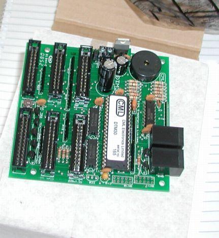
I have been extravagent and bought three new boards from CML electronics. The first to be implemented is a DTM30 board, which allows traditional style control of points and (reporting of signal and occupancy states) but using very modern techniques.

In a "traditional" panel you push a switch and it activates a point motor, this is OK, but it has several drawbacks -

Firstly, it means you have lots of wires flowing from the panel to the various motors.

Secondly, it means if, like me, you want to be able to control routes both by computer and from the panel then that is not possible without conflict.

Using this CML board, then there are no direct wires to the point motors instead the board outputs and inputs packets to the Digitrax loconet bus. These instruct the point motors to change state this is then "seen" by the computer and so it is aware, it is also seen by the static decoder on the point which actually activates the point. Similarly if the computer or "throttle" gives a command to change state of a point that will be picked up on the bus by the DTM30 which can track the change and change the indicator light.

This all means that you only need three connections from the board to the outside world - two loconet connections and a power supply.

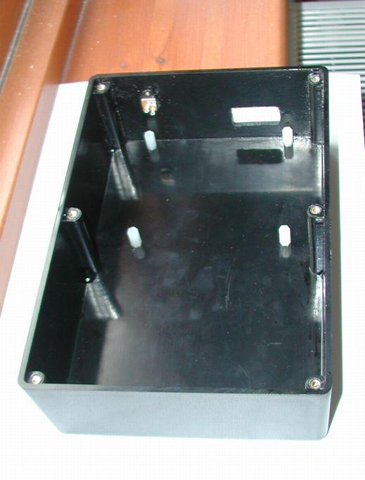
I used a maplin £4.99 ABS box, combined with some Hexaganol plastic spacers (12mm) to mount the board on off the floor of the box and a power supply left over from a BT broken home hub that gives up to 2A at 9V DC. I then connected that to a Chassis mount 2.1mm DC socket (FT96E) so that the whole box could be unplugged.

On the top of the box, I have used some 5mm green HB LEDs (CK39) mounted on 5mm LED Clips (YY40) and a sub miniature push switch (JM01B).

Like everything else this is just for test at the moment so I have not made the box too pretty.

I purely want to test out the concepts for the main layout. As so much wiring is involved I want to be sure what I am doing before I start.

/images0509/box.thumbnail.jpg /images0509/test_panel_leds.thumbnail.jpg /images0509/DTM30_board.thumbnail.jpg

New Test Layout

I have now moved into the new room - hoorah, and I have taken my single board layout and am working on turning it into a "tail chaser". I intend t use this layout to do a dummy run before I build a more seroious layout.

In particular I want to check out track laying (using glue rather than pins) and ballasting techniques, and most importantly I want to work on the electrical fit out to allow computer and panel control as well as throttle control.

Here is the current progress, with the cork layed.

/images0509/test_track_image.thumbnail.jpg /images0509/corked.thumbnail.jpg

Team Digital SMD 82

  • Can operate a pair of points from a single output

  • Operates on a switch transition rather than level

  • LED driven onl from tortoise?

  • poor to operate tortoise?

Heljan Western Disassembly

There are no retaining screws for the main body moulding.

But it is hard to grip anywhere - DO NOT grip the chassis by the fuel tanks as these are only held on by four skinny plastic clips and it is very easy to break them ( I speak from experience).

/images0509/fuel_tanks_warn.thumbnail.jpg

The best disassmbly mechanism is to insert two thin sheets of soft bendable plastic one on each side below the drivers door and lift one end of the body up using these pieces of plastic as levers.

/images0509/Body_Removal.thumbnail.jpg

DCC fitting - the pin 1 diagram is not that obvious on the instruction sheets - here is a picture that should hope make it clearer. I used a LENZ silver, the silver direct would NOT fit under the body

/images0509/insidewestern.thumbnail.jpg

Kadees - I used number 19s directly on the NEM sockets. They seemed to work fine.

Bachmann Mark 1 Disassembly

As part of a longer term plan to add lighting to the coaching stock, I needed to dismantle a Bachmann Mk 1 coach.

As always this was more fiddly, and stressful than one would like. As models have got more detailed, they have also got more delicate. So here for my failing memory, as well as anyone else out there - here is my guide to dismantling Bachmann Mk 1s.

  1. Remove Water Pipes

/images0509/waterpipe_location.thumbnail.jpg

Remove the water pipes on each end they can just be pulled out with pliers or tweezers, if you just remove the lower fixing they can be gently bent clipped around the side of the coach.

  1. Remove Bogies

Turn coach upside down and remove each bogies by unscrewing the centre screw.

  1. Remove Coupling Assemblies

/images0509/cmc.thumbnail.jpg

There are clever, but delicate little coupling assemblies below each bogie, these can be carefully unclipped.

  1. Unscrew the base

/images0509/retaining_screws.thumbnail.jpg

Three screws can now be seen and removed. and the seating slid from the chassis.

/images0509/sliding_seating_back_in.thumbnail.jpg

When you come to reassmble, please note that the middle screw is not in the centre, so the base and the floor need to be lined up - if you put one in the wrong way round, the middle screw can not be done up.

/images0509/bogie_one_way.thumbnail.jpg

Also note the bogies fit on with the 'gap' pointing towards the coupling socket.

Bachmann Standard 5MT disassembly / DCC fitting

Whilst I like this model enormously and it is equipped with a DCC socket - it is very tricky to carry out the fitting without damaging the plethora of delicate features on the model.

This is made unnecessarily worse by the lack of any good disassembly instructions....I hope this blog post will help others as some instructions turn a tricky prospect into a relatively simple one...it will also help me recall what to do when I have to it again.

To separate the body from the chassis requires three screws to be removed

Firstly the piece of the puzzle that I wish I had known was to remove the screw connecting the con rod to the rear driving wheel. This allows the connector from the con rod to the body - presumably this was the speedo connection on the protoype?...if you don't remove this then you end up like this....

PIC}:-oops.jpg;

The second screw to release is the countersunk screw at the front of the loco, indicated by the arrow in the picture below...

/images0509/front_fixing_screw.thumbnail.jpg

The last screw to remove is the hardest to find / get at , as it is hidden below what presumably are the brake actuating mechanism...but again my knowledge of the prototype is so limited that I am only guessing...In the picture below then I have labelled four components -

  1. brake rod running down the centre of the loco, is just clipped in place, can either remove completely or just unclip from the component marked '3' below and bent gently to one side

  2. can't be unclipped just have to bend out of the way.

  3. a 'nodding donkey' shape of component which is easily lost - clips each side and then has a locating lug holding it in place in the chassis.

  4. the screw we are trying to get at. Can't be seen on the next photo, look at the one below that.

/images0509/labelled.thumbnail.jpg

OK now you can separate the two halves of the loco, let's turn to the DCC decoder, I have used a LENZ silver 8 pin with plug. The only thing to note is that to fit in the nicely designed slot for it to go in, you should trim any heatshrink back tight to the edge of the little circuit board as here:-

/images0509/cropped_heatshrink.thumbnail.jpg

And here is a picture of the controller fitted into the loco - as you can see the controller is stood vertically in a slot designed for it mounted in the smokebox area.

/images0509/lenz_fitted.thumbnail.jpg

When reassembling the loco there is a plate that fits under the cab that will have come out when you separated the body from chassis. Here it is below...

/images0509/rear_plate.thumbnail.jpg

The plate fits back with the semicircular bit pointing to the front of the loco and the hole in that fitting over the lug highlighted in the next photo...

/images0509/rear_lug.thumbnail.jpg /images0509/Oops.thumbnail.jpg

Heljan Falcon DCC

This was a relatively easy one to fit, no screws to remove the body, just used four thin plastic strips to slip between the body and the chassis and it came off fairly easily.

One of the nice LENZ Direct (8 pin) decoders fits directly in and pop the top back on.

Unfortunately the couplings are going to be harder as there is much internet fuss about the fact that the skirt below the buffer beam has been glued on and will foul any couplers that are fitted...I think I'll wait and see what happens...

/images0509/silver_direct_fitted.thumbnail.jpg

Gash layout

As a result of building a very simple test layout - I have learnt a few things to jot down....

The test layout has curves of down to 31cm radius and up to 41 cm radius.

An awful lot of stuff wont go around the 31cm curves, and even stuff that does, tends to get buffer lock, with the kadee couplers.

Even the 41cm curves (measured only very roughly - I should do a better job measuring) seem to derail a fair amount of stuff. Which only just confirms the min. radius decisions for the plan (which is 65cm for any longer curves and 55cm at worst anywhere). This is still nowhere near realistic, but should at least reduce some of the most unrealistic look.

Also note Tim (a) wherever possible DO NOT MAKE JOINS ON CURVES it is very hard to keep them smooth and sweeping if you do. (b) for tighter stuff consider set track - esp if nonscenic.

Some people do not use track pins as they rightly say it ruins the look of the track I wonder how they manage to glue the track down if you do it on curves?

Must try the tillig elite track

Must try more point motor operation

Must do more kadee operation to check with my current fixing mechanisms with shunting and delayed uncoupling.

Heljan Falcon in Lime Green

Although there are some reported problems with buffer beam changes, I found that fitting a bog standard No. 19 Kadee worked with the standard (deep) buffer beam.

The model took an 8 pin Lenz silver direct DCC chip.

/images0509/falon_side.thumbnail.jpg /images0509/falcon_front.thumbnail.jpg /images0509/falcon_box.thumbnail.jpg /images0509/falcon_34.thumbnail.jpg

Standard Radius Curves and gradients

I am back to track planning as I now plan to hae a bigger room - woot!

Reading various articles, people often talk about standard radius curves in terms of a reference for tightness, e.g. in terms of what couplings can cope with - I have not been clear on what these equate to - so for my own reference here they are -

1st radius - 37.1cm 2nd radius - 43.8cm 3rd radius - 50.5cm 4th radius - 57.2cm

I have also been investigating gradients - the general consensus is that 1 in 25 (4%) is steep 1 in 50 (2%) ideal, I am planning on around 3% so I think I may get away with that.