
18 Sep 2014
Cork Paint
I sprayed a mixture of grey, red oxide and black primer on the cork. It isn't great (as you can see it is very patchy) but it doesn't really need to be - it is there just to ensure that when it is ballasted there isn't new shiny cork underneath.
For these boards I painted them in situ as taking them out was going to be difficult.

17 Sep 2014
Corking
Back to laying down cork; this time I have the additional problem that I want the edge of the cork to be a 60 degree angle where there is no platform and a right angle cut where there is a platform. This is further complicated by the fact that the platforms at Banbury (like at many stations) have a considerable overhang - I have looked at these for sometime (hard to measure without getting yourself arrested) I believe the overhang is about 9 inches.

The road bed needs to be wider where there aren't platforms too. In order to make marking and cutting the cork as accurate as I could, I printed out two full scale plans from xtrckcad - one with a roadbed width of X.Y, which I used where there was a platform and one with a roadbed width of A.B which I used where there was no platform. I then combined the two and used an angled cutter where there was no platform and a knife held normally for platform edges.


15 Aug 2014
The Dreaded Lifting Hatchway
After going all the way around the room I now need to complete the circuit with a lifting hatchway.
I was of course stupid to do this last as it is difficult enough without trying to get the levels on each side the same. I had to undo some of the woodwork that I first put together a few years ago in order to build out a base on which to mount the hatchway hinge side. I have used kitchen flap type hinges which are relatively narrow and allow the hinges to be separated later by removing the metal shaft.
The hatchway itself which is approx 85cm long (too long probably) is made of 12mm ply strngthened on each side by some 2 x 1. The hinges mount into the 2 x 1 through the ply for extra strength. I have made some stops for the hatchway to rest on when it is up, again not ideal but ok.
The whole thing is kept inline laterally by usine one DCC concepts alignment dowel pointing upwards from the base on the open side of the hatch (see the photos).
Finally I have put some wooden sides to the hatchway (painted gray to give the impression of bridge sides) to stop errant derailed trains running off the edge (a la the Tay bridge disaster). This is of course completely non-prototypical for the South of Banbury station but I am too old to go crawling underneath!


12 May 2014
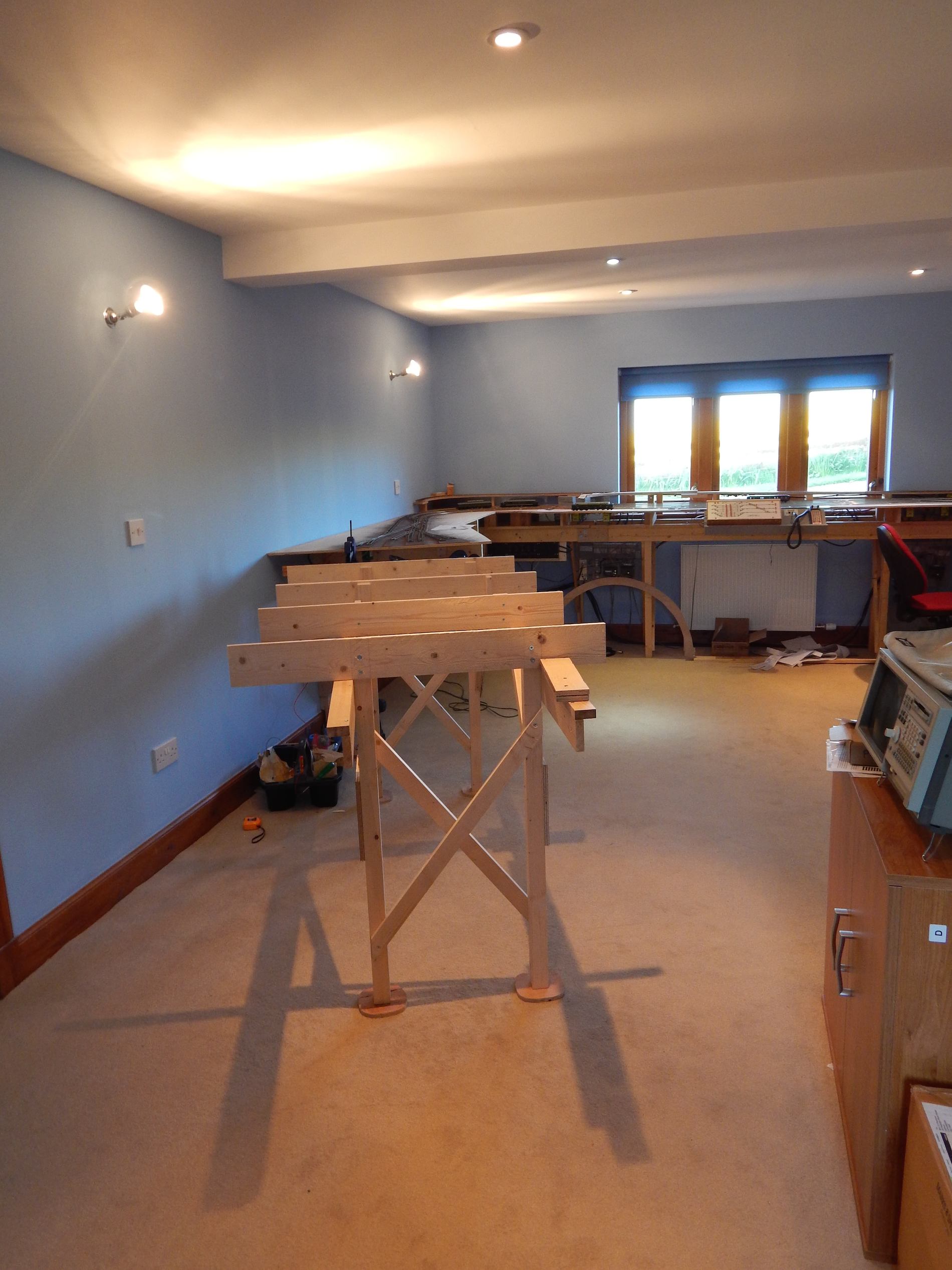
Woodwork
The main station board is big, and unlike every other board so far, is supported by a semi-free standing table. This table is like the rest of the layout is of L-girder construction.
One of the things I worried about in the room is what flooring to use. Normally a hard floor would be better for several reasons - less fluff to get in the works, and much easier to keep everything level. But we live in one of the coldest parts of the country and I just couldn't face a cold hard floor! To try and keep levels constant on a carpet I have cut large plywood feet for each of the legs on the table.
This isn't a problem for the rest of the layout as it is supported on brackets mounted to wall so doesn't care what level the carpet is!
I have used DCC concepts alignment dowels to match up the North approach board woodwork to the table that the station is going to stand on.


20 Feb 2014
Power Switch Unit Mounted
I have now mounted the power distribution switch unit - that I made ages ago. This has gone a little way to help tidy up the mass of wiring around the main power distribution board. Needless to say it was slightly trickier than I had hoped as I built the distribution switch unit before I knew precisely where it was to be mounted.

16 Feb 2014
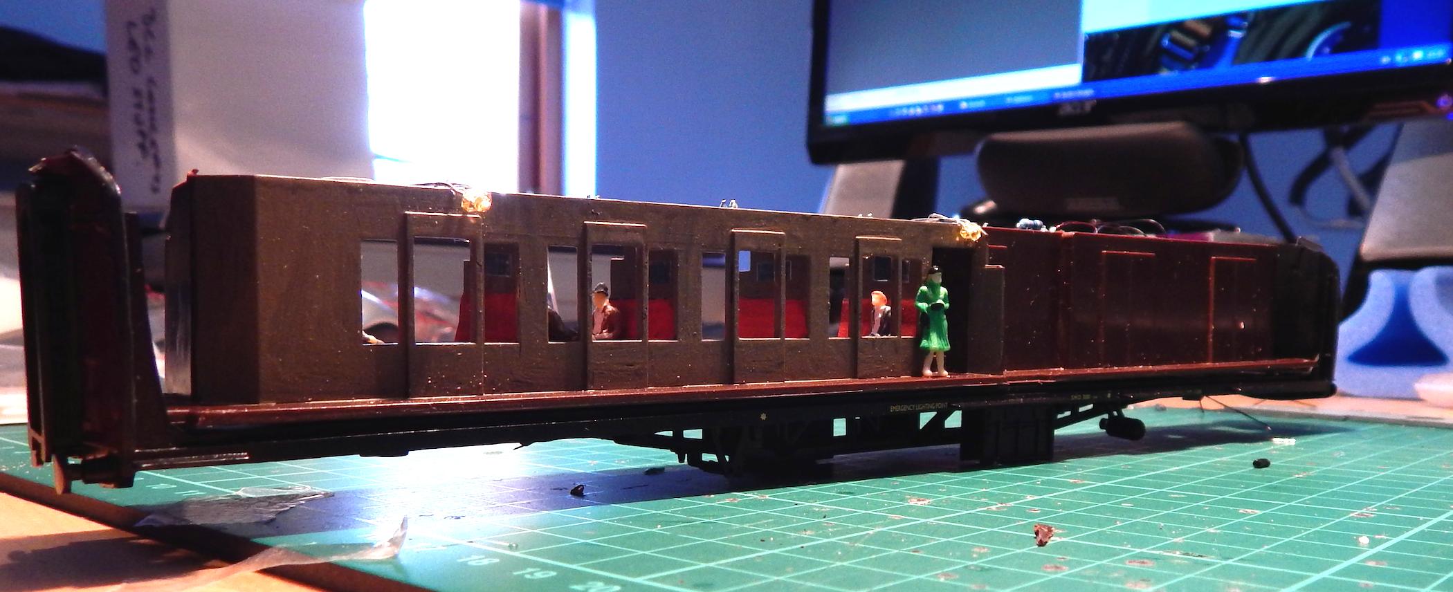
Bachman Mk1 Composite Brake
As a break from layout building I decided to have another go at putting lighting in a coach.
Doing a composite brake coach (half passenger seating half guards area) is the obvious stock to do - its easy to hide the electronics (in the guards compartment) - you can take oppotunity to put a red light on the back of the carriage and being typically the last coach in a set it is the one you most need to have live for occupancy detection.
I need various pieces of rolling stock to put a resistance across the rails to allow the detection software to see the full length of a train from the track occupancy detectors; putting lighting in has the side benefit of being "seen" electrically by the occupancy detectors. The other method is a simple resistor across - a wheelset.
When fitting lighting - getting the power from the rails into the body of the coach is, at least for me, still not a well solved problem. I use DCC concepts axle pickups (actually i use the replacement wheelsets that have the pickups already installed) and they do half the job ok. What that doesn't solve is getting the power from the bogies up into the body of the coach. At the moment I use very fine wire - but as an engineering solution I don;t like the method - it is often difficult to make the wires travel close to the rotation axis of the bogie - potentially causing resistance to their movement and it makes assembly and dissasembly hard.
I have decorated the internals of the carriage by painting the seats and by putting in ersatz mirrors (fine strips of sticky mirror like material) on the partition walls and adding some passengers.
The whole thing works ok, but personally i find the DCC concepts Flicker Free2 units don't completely eliminate the flickering - I think it might be more accurate to call them Flicker A-Bit-Less!

5 Jan 2014
More Appch Wiring
Still cracking on with the Northen Approach board wiring - getting bored with it now.
Whilst in some ways I wish I had bought DCC Concepts cobalt point motors instead of the Tortoise motors I am using (because their smaller size makes for less problems in squeezing them all in) One thing I like about the tortoises is that you can have a harness with an edge connector which you can just pull on or off as you are building.
In the picture you can see the blue edge connectors attached to some of the finished motors.

28 Dec 2013
A chance to make some progress
After a stupidly busy couple of months, the Christmas break has allowed a few days of fairly continuous work on the approach board (that I see from this blog I started in June).
I now have all of the points mounted on the northerly station approach board...
The flange screws you can see between the rails holding the trackwork in place are to allow for minor adjustments, the track will eventually be glued into place when the track is ballasted (at least a year away) and at that point the flange screws will be removed.
I want to check that the track runs perfectly before gluing it down.

I just can't work kneeling down for more than a minute or two so I have tried to make the construction of the layout as modular as possible - such that I can either work at my workbench or at least standing up. To that end the boards are all to some degree removable and the electronics are as modular as possible...
This board is the most complex, it requires 14 point motors and the track-work is split into 15 separate occupancy detection sections. This is because the complex station throat point work has so many possibilities that the required continuous track detection is tricky.
Continuous track detection means the computer never has to guess where a train is. It requires two things - (1) all track be occupancy detected (2) no single occupancy sensors are going to have two separate trains on simultaneously under normal operation.
The electronics for this board (like all of the electronics) hangs on hooks from a supporting L-girder in this case it contains 2 CML DAC-20 Digital point controllers and one Digitrax BDL-168 occupancy detector board.
The feeds to the track and points are mounted along the top on pluggable connector blocks, the feeds into the electronics are two cables attached on the right hand side by locakble circular connectors - one carrying the track feed and one the various power supplies required for the electronics.
There are 6 separate track feeds that come from two central Digitrax PM42 boards - these mean that any short circuit is more easily identifiable as it only affects one area of the track. One track feed goes to each of these hanging electronics boards. The whole board is assembled on the workbench and then can be plugged in when in position with no further wiring required, thus saving my knees.

5 Nov 2013
Hacked Slips
I Really like the modifications to the standard PECO point that DCC Concepts recommend in their very comprehensive downloadable cobalt instruction sheet. However for the double slips - which are expensive (£30+ ea) the thought of replacing the plastic sections with soldered copper clad was not for me, therefore I settled for trimming the plastic down to reduce the offensiveness of the original moulding...
Here you can see a sort of before and after

14 Sep 2013
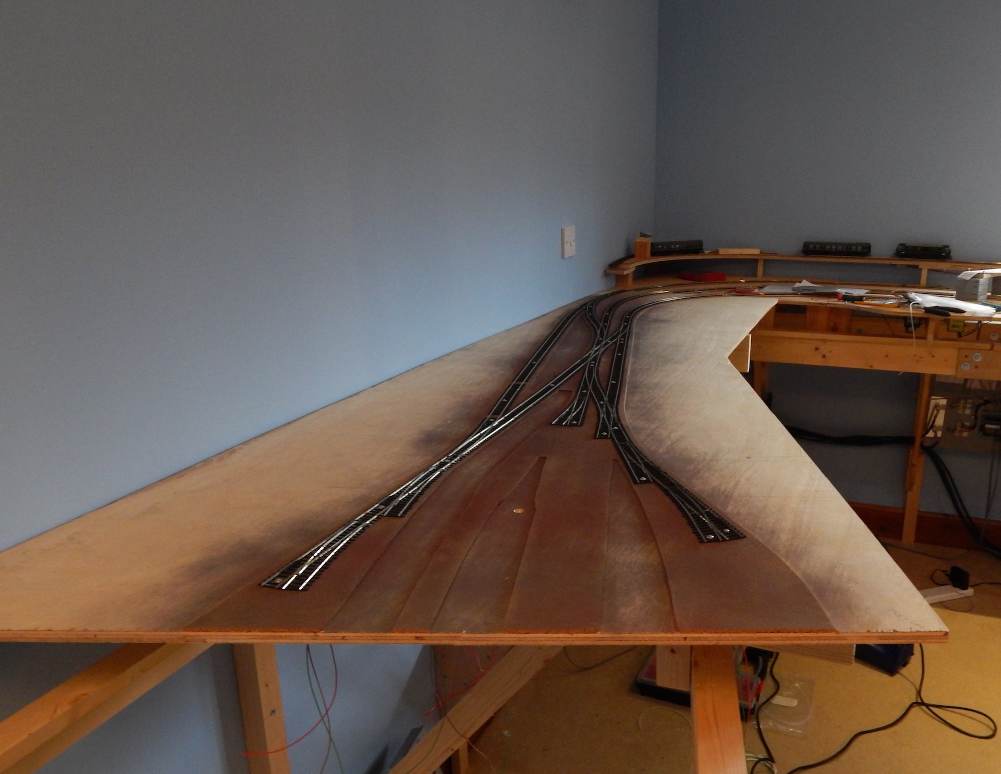
Some Vaguely Scenic Work
Up until now everything I have done has been on the non-scenic part of the layout. The station approach board is the first that has to be scenic, and whilst I don't want to get into the scenery yet, the one job I need to do before laying the track is to colour over the new cork and track bed so that when it is ballasted some years hence it will blend in nicely.
Here is the board with the cork laid on it

And here it is with a bit of colour

I am using the Chris Nevard recommended "misting" with cans of red oxide, matt black, and primer grey. It doesn't need to be a work of art right now because most of it will not be seen, all that is necessary is to remove the shiny newness of the cork and surrounding board.